Flowcharts & Control Flow
Before examining the use of control flow, let’s have a look at a way of visually representing the flow of instructions within code. A common way of doing this is to use a flowchart. A flowchart is a diagram used to represent a sequence of actions, so it’s perfect for representing a sequence of instructions (i.e., some code).
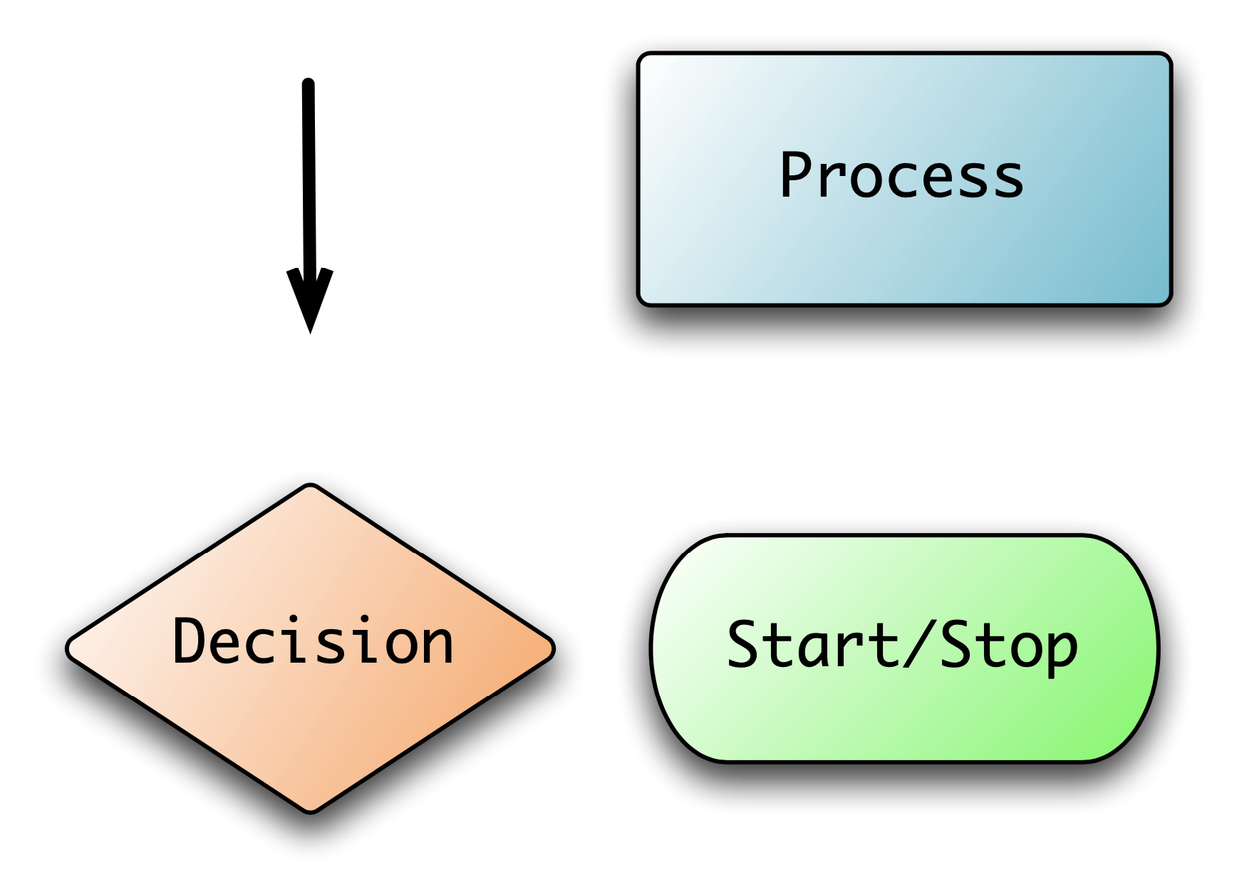
There are four basic flowchart symbols, shown in the figure below:
- Start/Stop: represents the start and end of the process. Typically, the start node has text to indicate the part of the code that is being visualised.
- Flow: point from one symbol to another to represent which action is to be performed next.
- Process: represents a task being performed. In our case this will be one or more simple statements (assignment statements or method calls). Each process can only have a single flow leaving it, as processes are performed in sequence, and should have text indicating what task is being performed.
- Decision: represents a point where the code needs to make a decision. This represents a location where we have a branching or looping statement. The text in the decision represents the condition that will determine which path is taken. A decision must have more than one flow coming out of it, and each flow should indicate the condition that triggers that path.
Structured Programming and Flowcharts
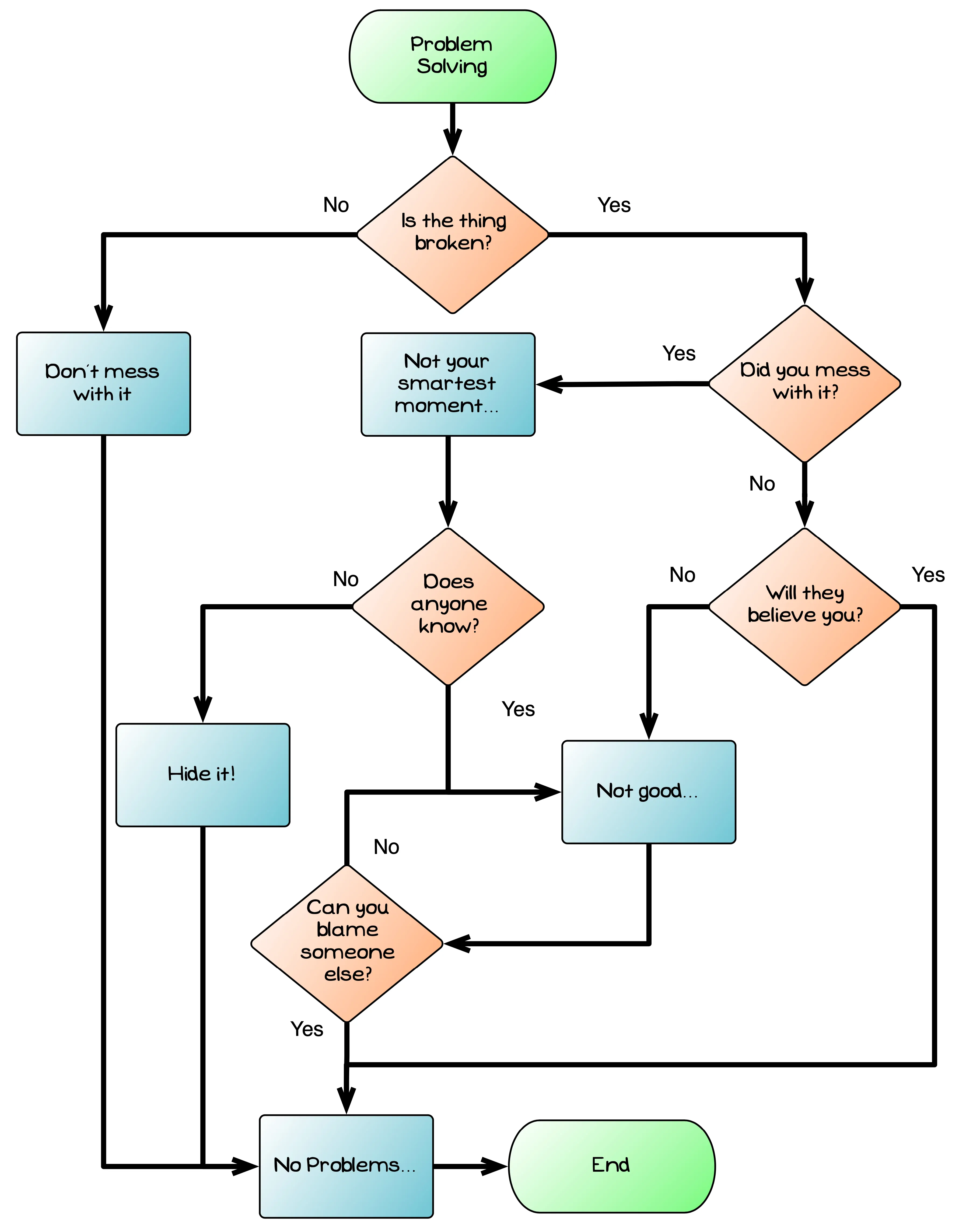
Flowcharts can be used to represent any sequence of actions, but not all sequences of actions will be easy to code. For example, the image below is a flowchart that captures a joke about changing things. This flowchart is not one that can be coded using the structured statements covered in this chapter. The reason for this is that there are some steps that appear in multiple paths. This makes it impossible to code using the structured programming principles.
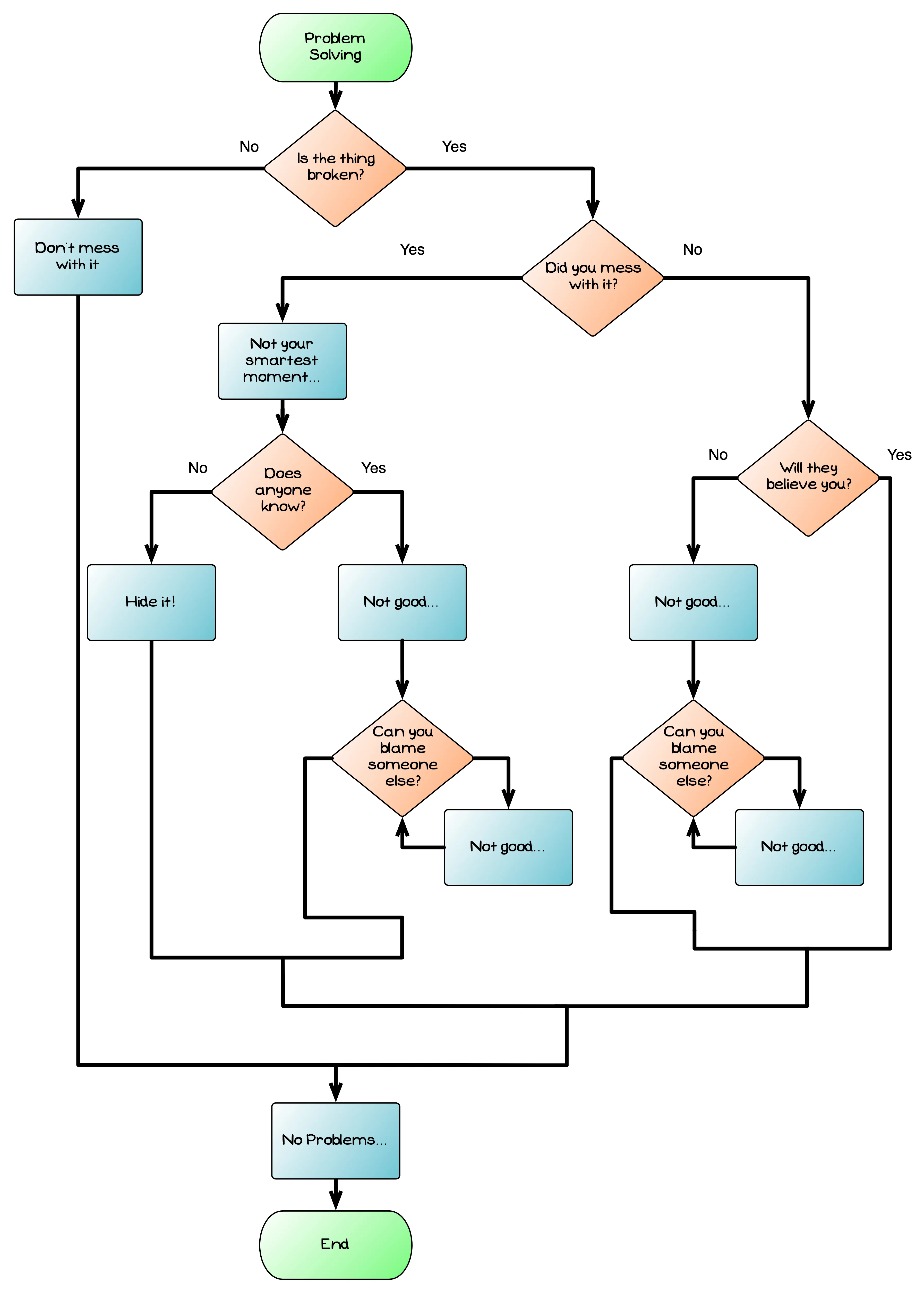
The image below shows a structured version of the same flow chart. Notice that in this version there are identifiable blocks, each having a single entry and a single exit. This structure could easily be converted to code using structured statements.
The structured programming principles indicate that code within our programs should be organised into blocks. These blocks match to the structured statements in modern programming languages: branching and looping statements. Each block has a single entry point and a single exit point, allowing them to be combined in a way that is easy to follow in the code. The addition of jumping statements to the language allows the blocks to have multiple exit points: one at the end of the block’s code, another at a break or continue statement. This provides extra flexibility, but still works within the general goals of the structured programming principles to help create readable code.
Hopefully you can see these principles as you compare the two flowcharts. Although the structured version does involve more processes, it also made it possible to organise them processes so that each block has a single entry and exit.
Designing blocks to achieve goals
In structured programming there are three kinds of blocks:
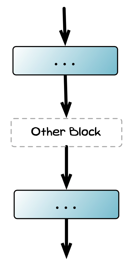
- Sequence: one instruction follows the next in a sequence.
- Selection: the ability to branch the sequence.
- Repetition: the ability to repeat a block a number of times.
Designing a program’s logic is all about figuring out how to combine these blocks to achieve the desired behaviour from your code.
You have already seen flowcharts for two of the blocks — the pages on branching showed selection via the if and case statements, and the pages on looping showed repetition via the while, do while, and for loop statements.
The flow chart snippet below shows what sequence looks like in a flowchart.
To recap, a flow chart showing selection will look like one of the following three blocks…

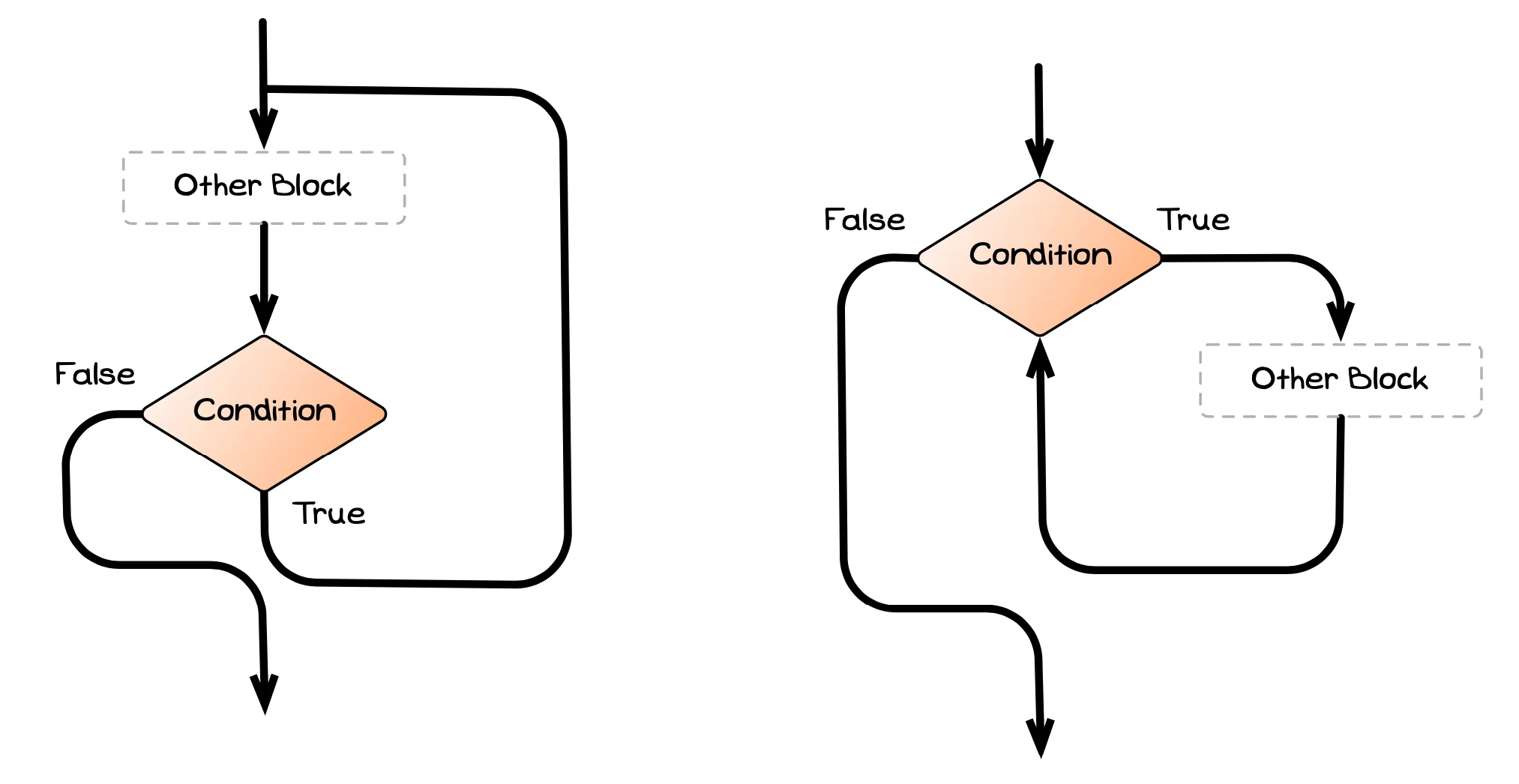
…and a flow chart showing repetition will look like one of these two blocks, depending on when the loop’s condition is evaluated.
