UML Class Diagram
When you start building object-oriented programs you want to be able to think about and communicate your design. In order to do this, developers created a graphical notation that can be used to communicate the classes that will be part of the solution. This notation is called a UML Class Diagram - where UML stands for Unified Modelling Language as it brought together a number of notations into an agreed standard format.

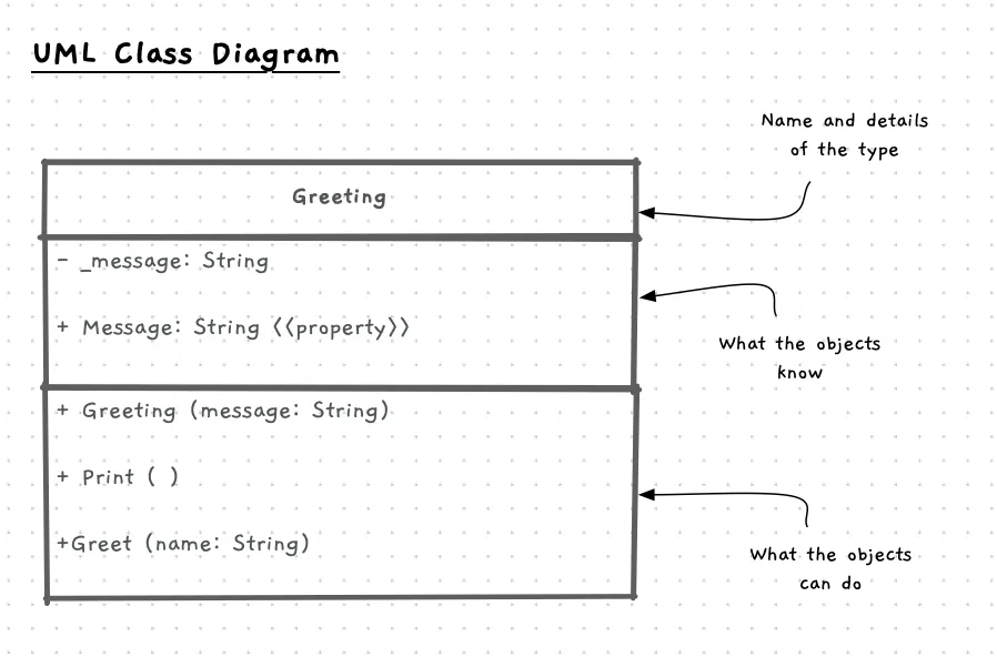
The above diagram shows the Greeting class in UML. This diagram captures the name, and responsibilities for the Greeting class.
In this diagram, each class is represented as a box divided into three parts. At the top you have the class name, this identifies which class you are describing. Following this you have the knows responsibilities which will list fields and properties. The final section contains the doing responsibilities.
Within the diagram you can add annotations using stereotypes - the text within <<...>>. In the above diagram we have added a stereotype to the Message to indicate this is a property.
UML Class Diagram: Why, When, and How
Class diagrams are a great way to think about and communicate the abstractions you are building within your program. When you start a new project you can quickly capture ideas and flesh out the design of your program using these diagrams. They provide enough detail that you can start to see how the classes work, but take much less time than writing up the code. This means you can check that your design works, rapidly changing the structure and allocation of responsibilities as you test different design options.
Once you have a design chosen, you then have the diagrams to help guide the code writing activities. This is where you get into looking at the lower level programming details we covered in Parts 1 and 2.